Page 1 of 2 12 LastLast
Results 1 to 20 of 22
  1. #1
    Member countyrookie's Avatar
    Join Date
    May 2006
    Location
    Blythewood, SC
    Posts
    1,033

    Question Possibly need a wiring diagram for 2006 HPDI VMAX VZ225TLR

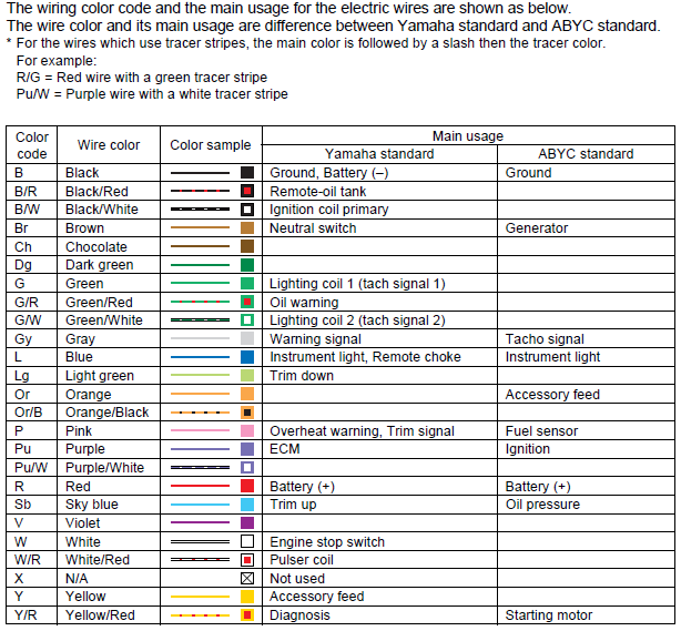
    So I'm in the middle of my winter upgrade on my Triton, switching from the two stock dual purpose gauges to four independent ones. I want to make sure I'm connecting all of this properly as it seems there isn't a "one for one" solution.

    Anyone have a wiring diagram or can point me in the right direct for the appropriate colors?

    Thanks in advance.

    Scott

  2. Member
    Join Date
    Feb 2018
    Posts
    3,195
    #2
    Wire colours can be all over the place. Very little standardization.

    Here are the Yamaha wire colours. God only knows what Triton used in the boat.


  3. Member countyrookie's Avatar
    Join Date
    May 2006
    Location
    Blythewood, SC
    Posts
    1,033
    #3
    LOL. Yam, that's encouraging. Thanks for the info though. Anything else would require me getting back to Triton in hopes that they know what they did back when? So. Much. Fun.

  4. Member
    Join Date
    Feb 2018
    Posts
    3,195
    #4
    Do you know what brand of gauges are in the boat?

    Most all will use a ground wire. Usually black.

    Then there is what I will call Key On power. Yellow from Yamaha. Purple from Mercury.

    Tachometer will need a signal wire. Green from Yamaha. Gray from Mercury I recall.

    If constant battery power is needed that is usually red.

  5. Member countyrookie's Avatar
    Join Date
    May 2006
    Location
    Blythewood, SC
    Posts
    1,033
    #5
    The Tach and Speedo are Motor Meter.

    Trim is Reminnbor.
    Fuel is Sucicago.

    I'm pretty sure we got the Speedo and fuel figured out, and the below helps greatly!

    All of the gauges came with some installation instructions in broken english at best.

    Quote Originally Posted by yam911 View Post
    Do you know what brand of gauges are in the boat?

    Most all will use a ground wire. Usually black.

    Then there is what I will call Key On power. Yellow from Yamaha. Purple from Mercury.

    Tachometer will need a signal wire. Green from Yamaha. Gray from Mercury I recall.

    If constant battery power is needed that is usually red.

  6. Member countyrookie's Avatar
    Join Date
    May 2006
    Location
    Blythewood, SC
    Posts
    1,033
    #6
    Ok, so here's an update. I had the fuel gauge working, blew and replaced a fuse, not working. Bought a replacement gauge, not reading, but getting power, cycling and lighting up.

    Tach and Trim still don't work, power and light. Not sure how to properly "program" the tach with the instructions I'm including.

    As far as wiring goes, I've tied all the grounds together. And all of the positive, signal and light wires together, both from the boat and gauges. I'm putting up the pics of the back of the old gauges so you can get a sense of the wires I've got coming to me from the boat.

    Any help is appreciated!Tach and Trim.jpgSpeed and Fuel.jpgFuel.jpgTach.jpg

  7. Member
    Join Date
    Aug 2021
    Location
    Nottaway Va
    Posts
    396
    #7
    Confirm the first photo is the tach and trim gauge? and the second one is the speedo and fuel?

    I think we can sort it out.

  8. Member
    Join Date
    Aug 2021
    Location
    Nottaway Va
    Posts
    396
    #8
    1st pic
    Black - ground
    grey - tach signal
    brown white stripe- trim signal
    purple - key on 12v
    blue - 12v / gauge back light

    2nd pic
    Large black tube - speedo tube
    Black - ground
    purple 12v key on
    blue - 12v backlight
    pink - signal for the fuel

    Each of you new gauges will need a ground, blue and purple connection. The exception would be a water pressure based speedo, then just a ground and blue for the back light. The old gauges did this internally through the plug. The new independent ones will need one each, so a split or jumper will be required. The sending unit/ signal wires will be teh only ones that are 1 for 1. If your new speedo is gps based, plug the large black tube with a machine screw and ziptie. The gps speedo will at least need a ground and 12v key on purple, maybe a blue if it isn't back lit internally.

    Programming the tach - those are little switches in that red rectangle. Take note of their settings on the old one, set the new one to the same.
    Last edited by XXXLTRP; 03-10-2023 at 05:26 AM.

  9. Member
    Join Date
    Feb 2018
    Posts
    3,195
    #9
    Don't you just love a lack of standardization?


  10. Member countyrookie's Avatar
    Join Date
    May 2006
    Location
    Blythewood, SC
    Posts
    1,033
    #10
    XXX and Yam,

    SO much fun. XXX, you got it right on the pics. The only thing on programming the tach is per those instructions, I don't understand the reading I need to get by pushing the button on the back of the Tach. I bought (I think) the same kind you used, so I don't understand what equals where the switch on the back of the old tach.

    Thanks again.
    Scott

  11. Member countyrookie's Avatar
    Join Date
    May 2006
    Location
    Blythewood, SC
    Posts
    1,033
    #11
    Yam,

    Not sure if you were being sarcastic, but I didn't have a green wire out of that plug and that was the speedo side. Now I'm trying to figure out how exactly I properly program the new Tach from Motor Meter to coincide with my dip switch 4 being open.

    Also, my trim gauge is working upside down. Any help?

    Other than that, all things seem to be a go. I did fire off the motor with no flusher attached and got one second worth of reading on the tach, so I know some kinda signal is getting there.

    Thanks again guys!

    Quote Originally Posted by yam911 View Post
    Don't you just love a lack of standardization?


  12. Member
    Join Date
    Aug 2021
    Location
    Nottaway Va
    Posts
    396
    #12
    Post a pic of the back of the new tach.

  13. Member
    Join Date
    Feb 2018
    Posts
    3,195
    #13
    I was not meaning to be sarcastic.

    Just commenting upon how three different manufacturers can use three different wiring colours for the same circuit. For the tachometer Yamaha uses green, Mercury uses gray and your tachometer maker uses black. Add in the other motor makers and it only gets worse.

    Yamaha uses a two wire ~ 300 ohm to ~ 10 ohm sender. Your trim meter may be designed for a sender with a different output.

  14. Member countyrookie's Avatar
    Join Date
    May 2006
    Location
    Blythewood, SC
    Posts
    1,033
    #14
    Thanks, and oh lord, maybe just go buy a Yam trim then?

    Quote Originally Posted by yam911 View Post
    I was not meaning to be sarcastic.

    Just commenting upon how three different manufacturers can use three different wiring colours for the same circuit. For the tachometer Yamaha uses green, Mercury uses gray and your tachometer maker uses black. Add in the other motor makers and it only gets worse.

    Yamaha uses a two wire ~ 300 ohm to ~ 10 ohm sender. Your trim meter may be designed for a sender with a different output.

  15. Member countyrookie's Avatar
    Join Date
    May 2006
    Location
    Blythewood, SC
    Posts
    1,033
    #15
    XXX, Here you go. New tach and the instructions.
    Quote Originally Posted by XXXLTRP View Post
    Post a pic of the back of the new tach.
    New Tach.jpgTach.jpg

  16. Member
    Join Date
    Aug 2021
    Location
    Nottaway Va
    Posts
    396
    #16
    I guess press the black rubber button til you get the speed ratio of 6, if your outboard is a 12 pole like you have highlighted in a previous post. I'm not sure where that will display? I've never seen one like that.

  17. Member countyrookie's Avatar
    Join Date
    May 2006
    Location
    Blythewood, SC
    Posts
    1,033
    #17
    Thanks, I'll see now that I have it set up. Only thing was I thought the old Tach was an 8. Yam911 put up that 12 pole highlight, and he's probably dead on with it. I just need to know what to do about the trim gauge. I'll be ok without for a while, but you know how it is when we like to see our stuff working properly.

    Quote Originally Posted by XXXLTRP View Post
    I guess press the black rubber button til you get the speed ratio of 6, if your outboard is a 12 pole like you have highlighted in a previous post. I'm not sure where that will display? I've never seen one like that.

  18. Member
    Join Date
    Feb 2018
    Posts
    3,195
    #18

  19. Member
    Join Date
    Feb 2018
    Posts
    3,195
    #19
    How Yam gets the trim sender information to a trim gauge.


  20. Member countyrookie's Avatar
    Join Date
    May 2006
    Location
    Blythewood, SC
    Posts
    1,033
    #20
    Thank ya sir!

    About that trim schematic, my gauge bought is 0-190 ohm. I'm guessing this is no good, and I should buy a yamaha brand?

    Quote Originally Posted by countyrookie View Post
    Thanks, I'll see now that I have it set up. Only thing was I thought the old Tach was an 8. Yam911 put up that 12 pole highlight, and he's probably dead on with it. I just need to know what to do about the trim gauge. I'll be ok without for a while, but you know how it is when we like to see our stuff working properly.

Page 1 of 2 12 LastLast