Page 1 of 6 123 ... LastLast
Results 1 to 20 of 109
  1. #1
    Member
    Join Date
    Apr 2012
    Location
    Texas
    Posts
    3,215

    Do it enough and....

    ... maybe I'll get good at it.

    Sooo... Decided to re-wire my electronics top-to-bottom. Last time I made some changes on the end(s) of the circuit(s). This time I'll be rewiring from the battery to the MFD.

    Gonna document it here for two reasons.

    #1) If I do something stup.... dum.... incorrect hopefully the electrical engineers among us...{hint... hint... MJ3} will grab me by the collar n' get me going in the right directions.

    #2) If someone else has been considering rewiring but wasn't sure where to start - maybe the information contained in this post will help.

    A lot of the stuff is still on the truck(s) headed this way from where ever but I'll post pics of what I've got so far.

    The goal of this li'l project is to eliminate any possibility that the 12v feed is the source of any interference that may show up in the images.

    Hats off to MicahaelJ3 for helping me with this project. I'm no electrical engineer - he is.

    I'm eliminating the dual buss bar that I've used since 2014. In it's place I'm using a Blue Sea #5025 6 position common source fuse block w/negative. The "Common source" means I have only one 12V lead that feeds the 6 positions. The "w/Negative" means I can terminate both positive and negative cables at the fuse block. This may seem like a no brainer to some but it's not a common wiring practice. It does lead to "issues" when routing the wires but I voted in favor of the simplicity of routing sheathed cable to a common destination vs splitting the sheathing much further up the cable. I suppose a case of 6 of one and 1/2 dozen of the other.

    Speaking of 6 position common source w/negative fuse block.... The 12v lead attaches at the top where the +'s are. The 12v Negative lead attaches to the bottom where the -'s are. The negative leads from each piece of equipment connects to the six lower position on the block leaving the upper six positions with fuse slots for the ATC fuses. On the left is the lock on cover that has label positions for each fuse position.


    In one of my other post I mentioned "ganged" spade connectors. While the power switch for my electronics was not ganged it did utilize spade connectors. But just thought I'd show what ganged spade connectors look like. They, on occasion, will come in handy when messing with factory wiring situations.

    Multiple spade connectors....


    Multiple spade connectors ganged up....


    As stated my old switch was a spade connector style and while I doubt it was causing any problems. The goal of this project is to eliminate things that "could" be a problem. Soooo.... The old spaded switch looked like this....


    I'm replacing it with a lighted switch(the old one was lighted as well) switch that accepts ring terminals. This, I hope, eliminates any possibility of a loose connection.

    Switch plus heat shrink crimp style ring terminal...


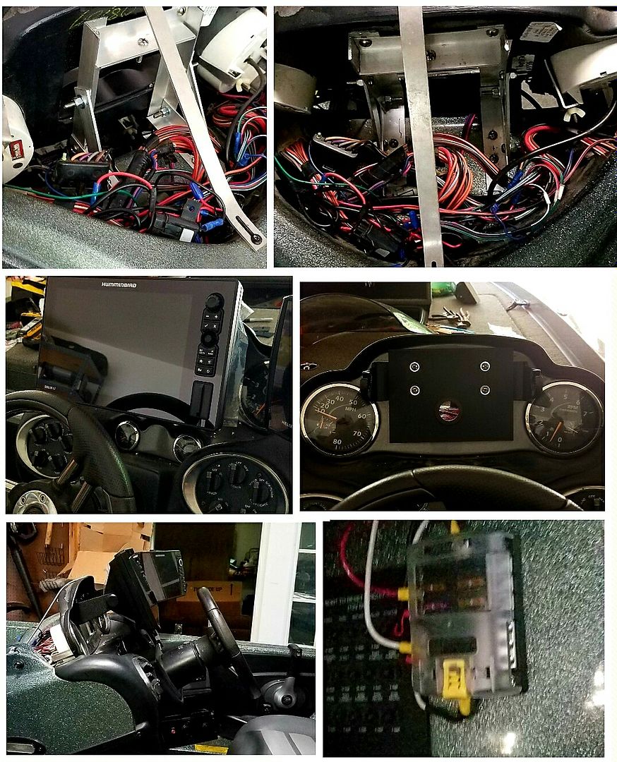
    I'm installing this fuse block on the side of the drivers console. There's really no "good" place and only a few that it'll even fit... even though it's pretty small.

    It's going on the other side of this console.


    Which, although I missed with the photo, you can kinna see where I sanded it with 50g paper to prepare it for epoxy bonding.


    Prepped the back of the fuse block as well. Then wiped both down with lacquer thinner.


    I use these, and lots of'em to keep the wiring secured. Because I'm working in the console area there's really no place to use bolts/nuts, screws or other types of fasteners. These are Anchor brand self-stick type. I've used the self-stick from Lowes/Home Depot and usually just soak'em in thinner, remove the self-adhesive pad and epoxy them in place. Because these are Anchor brand I'm gonna try using their self-adhesive feature. If it doesn't work.... I'll epoxy them in place.


    If there's no interest in this project post someone please be kind enough to let me know n' I'll not bore folks with the details... Thanks!
    Last edited by yupitsme; 06-08-2019 at 01:11 PM.

  2. Banned
    Join Date
    Aug 2011
    Location
    Boerne & Three Rivers, Texas
    Posts
    18,061
    #2
    I still think you’re certifiably crazy; but do please, carry on.


    How you gonna isolate the grounds from the stealth one though, as I mentioned before I was getting feedback from mine.

  3. Member
    Join Date
    Apr 2012
    Location
    Texas
    Posts
    3,215
    #3
    Quote Originally Posted by grout-scout View Post
    I still think you’re certifiably crazy; but do please, carry on.


    How you gonna isolate the grounds from the stealth one though, as I mentioned before I was getting feedback from mine.
    Last time on the water I put a Grp31 Platinum on the back deck and moved the leads that go to the electronics only switch/buss to that battery. It had absolutely no impact on the images.

    One thing I do you may not. I have a standard 4 gauge battery cable that is hard wired from the negative post on my #1 Trolling battery to the negative post on my cranking battery. Among other things that eliminates the need to run a separate Stealth One cable to the negative post on the cranking battery. Also provides common ground for virtually any electronics in the boat..... So I was told anyway...

    In the following picture my "common" ground lead is at the bottom. The cranking battery negative post is under the fuel fill/vent line. What the picture depicts is how I have a short lead clamp connected to the positive post of my #1 trolling battery. In the picture it is deployed in the "jump" mode for the cranking battery. Typically the clamp is simply clamped to the plastic nut of the battery hold down.


  4. Member
    Join Date
    Apr 2012
    Location
    Texas
    Posts
    3,215
    #4
    Oh... and.... one of the reasons I'm going with the fuse block is it eliminates the inline fuse holders. Those inline holders are kinna hard to label where they're "all" readable. Require 2 additional splices that could be source of problems later on and trying to lace up the wiring so it's neat and secure is a bit problematic with them there. Soooo POOF! they're gone!

  5. Banned
    Join Date
    Aug 2011
    Location
    Boerne & Three Rivers, Texas
    Posts
    18,061
    #5
    Yeah I don’t blame you for getting rid of the inline fuses, they are kind of junky anyways.

  6. Member
    Join Date
    Jul 2011
    Location
    Woodville, Al
    Posts
    421
    #6
    Disconnect the ground from the trolling motor battery to the cranking battery.

    Use 8 AWG from the cranking battery to the fuse box. Add a switch so you can kill power to the fuse box. And run 8 AWG to the bow units from the fuse box.

    Disconnect the stealth from the cranking battery.

    Test everything out on the water this way first to see if you have interference. Isolation is key.


  7. Member
    Join Date
    Apr 2012
    Location
    Texas
    Posts
    3,215
    #7
    What/where is that bundle of wires in the first two pics???? That’s pretty messy. Wouldn’t even begin to know how you trouble shoot that...

  8. Member
    Join Date
    Jul 2011
    Location
    Woodville, Al
    Posts
    421
    #8
    Quote Originally Posted by yupitsme View Post
    What/where is that bundle of wires in the first two pics???? That’s pretty messy. Wouldn’t even begin to know how you trouble shoot that...
    It's pretty simplistic if you know what you're doing. Anyway, the wiring harness you're referring to is for the console gauges and switches to the left panel controls.

    The bracket was installed to support a larger display.
    Solix 12 Gen2 Mega+ SI, Helix 7 DI G3, Helix 10 G3N SI +, Helix 9 G3N SI +.
    Upgraded to Mega imaging from a HDS-12 Carbon

  9. Member
    Join Date
    Apr 2012
    Location
    Texas
    Posts
    3,215
    #9
    I will say everything seem readily accessible!

  10. Member
    Join Date
    Jul 2011
    Location
    Woodville, Al
    Posts
    421
    #10
    The blue sea's fuse block is great. I've installed many of them, highly recommended.

    However, I highly suggest you isolate everything as suggested and test out the system. Connecting the grounds like you have them can induce a problem.
    Solix 12 Gen2 Mega+ SI, Helix 7 DI G3, Helix 10 G3N SI +, Helix 9 G3N SI +.
    Upgraded to Mega imaging from a HDS-12 Carbon

  11. Member
    Join Date
    Apr 2012
    Location
    Texas
    Posts
    3,215
    #11
    My ground architecture has been as I posted since 2010. I’ve been through 522c, Gen 2, a Gen 3 and my Carbons between then and now. I’ve had stellar images in the past with wiring as configured. As stated earlier I moved the current electronics buss/switch wiring to an independent isolated battery. It made no difference. It wouldn’t IF my power leads were picking up EMI/RFI from the rigging compartment to the electronics only switch. Installing 10 ga twisted wiring from the battery to the fuse block, sans a short segment at the switch, will take care of some of that. Ferrite rings triple wound just prior to terminating at the fuse block will handle the rest. New power only leads (2-wire) will address any concerns that the cut off NMEA 2000/183 may be an issue. Additionally each of the 4 power cables, 3 - Carbons 1 - SS3D, module will have triple wrapped ferrite rings at the connectors. The stated goal is to provide clean 12v power to the electronics equipment. I believe what I have planned will accomplish that.

  12. Member
    Join Date
    Jul 2011
    Location
    Woodville, Al
    Posts
    421
    #12
    Quote Originally Posted by yupitsme View Post
    My ground architecture has been as I posted since 2010. I’ve been through 522c, Gen 2, a Gen 3 and my Carbons between then and now. I’ve had stellar images in the past with wiring as configured. As stated earlier I moved the current electronics buss/switch wiring to an independent isolated battery. It made no difference. It wouldn’t IF my power leads were picking up EMI/RFI from the rigging compartment to the electronics only switch. Installing 10 ga twisted wiring from the battery to the fuse block, sans a short segment at the switch, will take care of some of that. Ferrite rings triple wound just prior to terminating at the fuse block will handle the rest. New power only leads (2-wire) will address any concerns that the cut off NMEA 2000/183 may be an issue. Additionally each of the 4 power cables, 3 - Carbons 1 - SS3D, module will have triple wrapped ferrite rings at the connectors. The stated goal is to provide clean 12v power to the electronics equipment. I believe what I have planned will accomplish that.
    Again 8 AWG would be recommended given the load demand and distance.

    Adding a ferrite ring can help reduce EMI by impedance matching however, how are you going to know what you need to match?

    Why wouldn't you take the simple approach first? It will avoid headaches and delays.

  13. Member
    Join Date
    Apr 2012
    Location
    Texas
    Posts
    3,215
    #13
    Quote Originally Posted by jjjaymmman View Post
    Again 8 AWG would be recommended given the load demand and distance.

    Adding a ferrite ring can help reduce EMI by impedance matching however, how are you going to know what you need to match?

    Why wouldn't you take the simple approach first? It will avoid headaches and delays.
    #1) The ampacitiy chart I’m referencing indicates. 10 ga is good for 10 amps with a 30’ run. I’m at less than 8amps.
    #2) I’m employing the ferrite rings recommended by a bonafide electrical engineer. He will have to provide the answer to that question. All I know is triple wrapping covers a humongous range of “could be’s”.

    I suppose simplicity is in the eye of the beholder. To me it’s simpler to move forward with my stated agenda. If testing indicates all is well and I’m satisfied with the results - I’m done. Doesn’t get much simpler than that. If I’m not satisfied with the results. Then I can start undoing things. As it is my boat is in my shop. To have access to that which I need access to I’ve removed both trolling batteries. I’m doing additional work organizing, securing and labeling. These actions are not a waste of time. In the end I’ll probably remove hydraulic steering lines simply so I can get electrical cables routed the way I want them and the way the should be. That means I’ll have to bleed the hydraulic system - again. I know the things I’m doing will:

    1.) Make electrical circuit identification easy.
    2.) Make physical plant outages near non-existent.
    3.) Make trouble shooting, should it be required, simple.
    4.) There is no doubt what I’m doing will clean the 12v supply to the electronic equipment. Will it help? Does it even need help? I dunno. What I do know is it can’t hurt.

    Jjjjjjjjj I’m not getting on you with my next comment. It’s just a fact I’ve seen over and over again. People like you will never understand people like me. Just won’t....

  14. Member bloodman's Avatar
    Join Date
    Oct 2008
    Location
    Belvidere, Il
    Posts
    6,010
    #14
    Not sure the deal but I know its entertainment at the least and educational at the most.
    At first I thought you were nuts. Now I think you da man. Lol.... crazy stuff but awesome too.
    I give ya

  15. Member
    Join Date
    Apr 2012
    Location
    Texas
    Posts
    3,215
    #15
    Tanks!

  16. Banned
    Join Date
    Aug 2011
    Location
    Boerne & Three Rivers, Texas
    Posts
    18,061
    #16
    Quote Originally Posted by bloodman View Post
    Not sure the deal but I know its entertainment at the least and educational at the most.
    At first I thought you were nuts. Now I think you da man. Lol.... crazy stuff but awesome too.
    I give ya

    Oh he’s nuts and I fully understand his nutsness. I think it’s a self-employed thing. No matter what we do, we always find a fault with something.

  17. Member
    Join Date
    Jul 2011
    Location
    Woodville, Al
    Posts
    421
    #17
    Quote Originally Posted by yupitsme View Post
    #1) The ampacitiy chart I’m referencing indicates. 10 ga is good for 10 amps with a 30’ run. I’m at less than 8amps.
    #2) I’m employing the ferrite rings recommended by a bonafide electrical engineer. He will have to provide the answer to that question. All I know is triple wrapping covers a humongous range of “could be’s”.

    I suppose simplicity is in the eye of the beholder. To me it’s simpler to move forward with my stated agenda. If testing indicates all is well and I’m satisfied with the results - I’m done. Doesn’t get much simpler than that. If I’m not satisfied with the results. Then I can start undoing things. As it is my boat is in my shop. To have access to that which I need access to I’ve removed both trolling batteries. I’m doing additional work organizing, securing and labeling. These actions are not a waste of time. In the end I’ll probably remove hydraulic steering lines simply so I can get electrical cables routed the way I want them and the way the should be. That means I’ll have to bleed the hydraulic system - again. I know the things I’m doing will:

    1.) Make electrical circuit identification easy.
    2.) Make physical plant outages near non-existent.
    3.) Make trouble shooting, should it be required, simple.
    4.) There is no doubt what I’m doing will clean the 12v supply to the electronic equipment. Will it help? Does it even need help? I dunno. What I do know is it can’t hurt.

    Jjjjjjjjj I’m not getting on you with my next comment. It’s just a fact I’ve seen over and over again. People like you will never understand people like me. Just won’t....
    My suggestions come from over 20 years of experience in the field (both military and civilian).

    I understand people who wish to stick to their current plan, it's not complicated concept. It's also a great learning experience for you.

  18. Member
    Join Date
    Apr 2012
    Location
    Texas
    Posts
    3,215
    #18
    Quote Originally Posted by jjjaymmman View Post
    My suggestions come from over 20 years of experience in the field (both military and civilian).

    I understand people who wish to stick to their current plan, it's not complicated concept. It's also a great learning experience for you.
    For sure there's some learning going on. And on the other hand this isn't my first foray into electronics cabling. One thing I find extremly beneficial when someone offers advice is if they'll take the time to explain, in some detail, why they're making that recommendation. Also... level/degree of experience with the topic at hand will lend some validity to those recommendations. 20 years is some serious experience in the field but I don't know how to translate that to the project(s) at hand. This is curiosity talking here but - precisely what is it you do/did in the field for 20 years?

    You may understand sticking to the current plan. Where it gets cloudy is the "why" behind that plan. On my last outing the images I was getting were pretty good. Side better than down but for the most part acceptable. But... there was this band of "stuff" from 20' to 30'. I thought it was something in the water column. Some called it interference. I honestly didn't/don't know. This li'l exercise is an attempt to find out. So I have a singular goal of trying to eliminate a debatable flaw in the image. Then I start chunking "might as well's" on the project pile. It's those "might as well's" that are creating the bulk of the work! Also I'm curious is perhaps some stray noise is affecting the image. Is there something going on with the software/hardware that is detecting signal interference and engaging some filtering algorithm that, while filtering the interference, is also degrading the image?

    When folks start suggesting I do things - add a switch. Or eliminate grounds between trolling battery and cranking battery. This indicates to me that the one doing the suggesting has not actually read/understood what I've documented in previous post. In this case there is a switch between the fuse block and the battery. Has been since I first installed electronics on this boat. Heck, I even posted picture of the old switch and of the new switch and explained why I was installing the new switch. Eliminate grounding issue possibilities. In previous post I've documented that I installed a stand alone, isolated group 31 Sears Platinum battery on the rear deck and swung the "Electronics Only" leads from the cranking battery to the test battery - nothing changed. Soooo... In my mind the problem, if there is a problem, lies primarily between the cranking battery and the Electronics Only switch/buss bar(soon to be fuse block).

    So... let's say I get everything buttoned up and put it on the lake and - nothing changes. Did I waste my time. Some will say so. Some will agree that what I did was beneficial in other ways and wasn't a total waste of time. I'm in the second group.

    Just to clarify something. All I'm trying to do with this particular post is explain that while it may seem like I don't/didn't think your recommendations worthwhile the fact of the matter is for the most part, sans the 8ga. recommendation, I had already done what you were suggesting. I would like for you to stay involved and continue to offer suggestions. Trust me.... I do consider all offers of help. May send me off on an unintended tangent but that's not unusual either.

  19. Member
    Join Date
    Apr 2012
    Location
    Texas
    Posts
    3,215
    #19
    Care package arrived yesterday...

    I've grown weary of stacking/un-stacking ring terminals at the battery when I need to de-energize a circuit. Plus all of the circuits have the dreaded in-line fuse monster. While the following solution does not eliminate all the ring terminals on my cranking battery it gets most'ov'em. As you can see it has 4 fuse positions, clear cover for the positive side and places to install circuit identification lables.


    I spoke of "might as well's" in the previous post. One of those might as well's involves new leads from engine to cranking battery. When I originally installed the engine I cut the battery leads just a tad too short. It works but I didn't like it. Welp... here were are 10 years later addressing that issue.


    Now.... gotta crimp n' cover those 4ga lugs. Some folks use a hammer style crimper. Hell... I suppose some folks use vise grips. Some time back I found this hydraulic crimper at Harbor Freight and with some exceptions it works well. It's got dies that don't actually fit anything. But they are hex crimping dies that if you apply the crimper multiple times/steps it produces a really nice looking hexagon crimp. Before crimping the lug on I put dielectric grease on the cable end and in the lug opening. As you can see in the previous photo I'll also cover/protect the crimp with adhesive lined heavy duty heat shrink tubing. I make up as much of the cable at the work bench as I can. That way I can clamp the crimper in the vice and handle the wiring/lug position with both hands.


    Then of course the ORIGINAL purpose of this project. Replace the leads from the battery to the switch. And for that I'm using Pacer brand type III Marine Wiring. Marine wiring, if it's truly marine wiring, is tin coated copper strands. There is Type II and Type III. Both are stranded conductors. The Type III is a finer stranded conductor and better suited to the rigors/vibrations found in the bass boat environment. If I'm wiring the Queen Mary Type II would be just fine.


    Some "before" pictures of cranking battery wiring. These are with the terminals already disconnected to it's a bit messy'er that usual. Except for the dreaded in-line fuse holders. That just a mess period.


  20. Member
    Join Date
    Apr 2012
    Location
    Texas
    Posts
    3,215
    #20
    Was disassembling some connections at the battery and figured I'd post one of my earlier solutions that was beneficial to me. If you have a lot of connections coming back to the battery ring terminal connectivity becomes a big issue on some batteries. Heck on any battery. I've got six positive side ring terminals that I need to connect to the cranking battery - not counting the main engine battery cable.


    Disconnected they look like....


    Soooo... that's why the 4 position fused attachement is going to come in handy...

    And just because I was back there disconnecting things though I'd post a pic of another "anal" thing I do. Ever been on the water and needed to do something with batteries or battery connections? I have. So now tucked away in my rigging compartment is this water proof bag that hold everything I need to disassemble/reassemble anything battery related.


Page 1 of 6 123 ... LastLast