Page 1 of 2 12 LastLast
Results 1 to 20 of 21
  1. #1
    Member
    Join Date
    Apr 2016
    Location
    Oklahoma City
    Posts
    451

    Thumbs Up Carburetor Link and Sync, or Sync and Link, for Yamaha Outboard

    On the old Pro V you can't hardly find any link and sync tips online. It's mostly newer engines with fancy computer equipment put into the intake bolt holes to see if it's firing on the right mix. Those (afaik) don't work on the older, non fuel injected versions so here's my attempt to go through a full sync & link for my P175. The process should be similar for most any Yamaha outboard in the 1990s to maybe 2001 or so.

    First, disconnect the battery and pull the emergency line by the key so the engine won't start.
    Take out the top starboard top spark plug (go ahead and make sure it's clean and gapped at 0.035 now...) and stick a dial caliper depth gauge or dowel rod in there till it touches the piston.
    Now turn the flywheel on top with one hand while you press in on the dowel rod with the other. The piston will go up and down.
    When it's at the very top and just about to go back down (easier to see with a dial caliper), stop turning the flywheel and take note of the depth of the rod or caliper. From memory, I think mine was 0.13". This is your TDC, or top dead center. Now we're going to set the flywheel pointer for timing.

    Turn the flywheel another round until the piston is coming back up.

    Now I'll walk you through 115hp models, then give you the numbers for the rest.

    For 115HP model stop turning at exactly 3.91mm (0.15 inches) longer than where your top dead center was. For instance, if your TDC was 0.13, then we stop turning the flywheel when the piston is on the upswing at exactly 0.15 more than 0.13, or 0.28 inches. Now freeze everything and jump up on the boat. See the flywheel pointer thing that tells you the timing? That's the flywheel timing plate. Set the flywheel timing plate (pointer thingy on the front) at 25* BTDC and tighten it down. Maybe put some blue locktite on it for good measure.

    For 130/L130, turn it to 3.05mm (0.12 inches), timing plate pointer at 22* BTDC
    For 150/L150, turn it to 3.61mm (0.14 inches), timing plate pointer at 24* BTDC
    For ProV150, turn it to 4.88mm (0.19 inches wow!), timing plate pointer at 28* BTDC
    For 175, 200, and L200 turn it to 2.53 (0.10 inches), timing plate pointer at 22* BTDC
    For ProV200, turn it to 3.05mm (0.12 inches), timing plate pointer at 20* BTDC

    That's it for the timing plate pointer, now you're starting from a true number instead of just trying to guess!

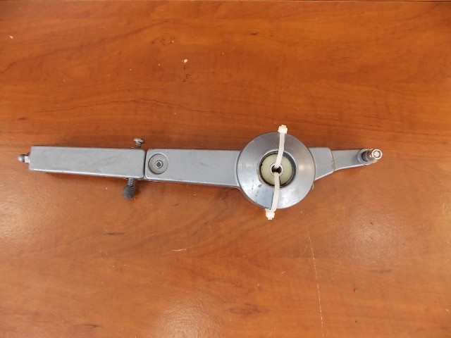
    Now look at your magneto control arm. It looks like this, only going up and down in there instead of lying on a table. If yours is lying on a table, don't bother setting your timing. You have bigger problems!


    Measure the distance of the snap-on screw connector on the top of the control arm going to the metal thing under the flywheel with your dial caliper.
    For 115 - 130 hp it should be 60mm, or 2.36 inches.
    For 150-200, it should be 54mm, or 2.56 inches
    for ProV200, 63mm or 2.5 inches.


    Measure the distance of the similar connector on the right side of the control arm also. That's called the Throttle cam control link.
    For 115 - 130hp it should be 53mm, or 2.09 inches
    For 150-200, 42.5mm or 1.67 inches
    For ProV200, 61mm, or 2.38 inches
    For 225 it's 72mm or 2.83 inches

    Now turn your flywheel until the pointer points to 4 degrees ATDC (this is the short marks before 0 on the flywheel) for 150-130hp models.
    Turn it to 6 degrees ATDC for 150-225 models.

    Now adjust the "full retard" (Hahahaha! So relevant!) screw, that's the screw going from right to left and holds the arm away from the engine. On the bottom of the flywheel there is a very hard to see line. It should be near the line (looks like an arrow pointing outward) on the connection to the control arm. Line these two marks up by screwing the retard screw in or out.

    That's it for the throttle link.

    Now we can work on the carbs themselves. Be proud of yourself!

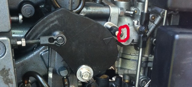
    Loosen the roller adjusting screw here by turning it clockwise. It's a backwards turning screw, be aware!


    Loosen the throttle arm adjusting screw too. There's one on 115 and 130 hp models, two on 150-200hp. This pic shows a 175model.


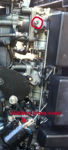
    Count the turns you take and write them down as you loosen the idle adjusting screw too until it isn't touching anything underneath anymore. It's behind the linkage.


    Now verify that the deep butterflies on the inside (usually gold) of the individual carbs are fully closed - not the butterflies on the outside, those are operated by the choke - and tighten the screws up again by turning them LEFT. If they're not closed, wiggle the linkage you just adjusted to make them close, verifying they move freely. If necessary, hold them closed (your spring may be weakened by age) and tighten the screws by turning LEFT (opposite to the rest of the world) so that they are held in the closed position.


    Now tighten the idle adjustment screw until it just begins to open the gold butterflies again. Once it just begins to open, turn it one full turn. You'll adjust this to within spec (below) once you start the motor.

    Idle RPM Spec:
    115 - 130 hp: 750 RPM plus or minus 50.
    150 - 175 hp: 700 RPM plus or minus 25.
    225 hp: 750 RPM plus or minus 25.

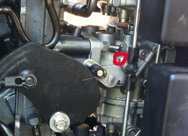
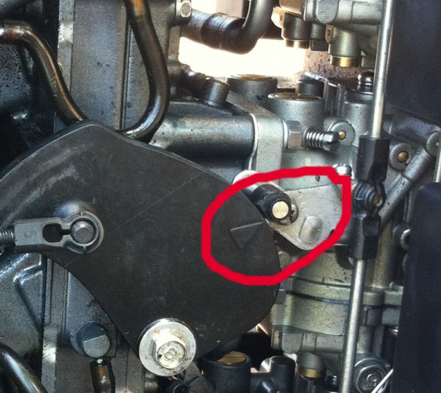
    Now for an iffy part. Several people have reported that this NEVER lines up for them. If you did the above correctly, you should loosen the screw here again and push it down so that it touches the big plastic disc looking thing with an arrow on it. It should hit right where the arrow points. Then tighten it back up.


    Now put muffs on the motor and start her up. Give it about 10 seconds to run any excess gas or anything through there and straighten out, then adjust that idle screw again until it's within spec (above). That's about it I think. Hope this helps some of you. (and hope I got all the steps in there!)

    If you need to fiddle with your idle adjustment screws, here's the specs for those. Turn them inward until they're lightly seated, do not tighten! Then loosen them...

    115hp - 5/8 of a turn
    130hp - 7/8 of a turn
    ProV150, 200, and 200L - Port side, 1 1/4 turns, Starboard side 3/4 of a turn.
    150, 175, and 225 hp - 1 1/4 turns out.
    ProV200 - 1 3/8 turns out.
    Last edited by SkeeterStew; 07-06-2017 at 05:17 PM.
    Need a new bow step pad for your boat? Do what I did!
    http://www.bbcboards.net/showthread.php?t=712307

    Are your boat seats trashed? Fix them yourself and save $1000!
    http://www.bbcboards.net/showthread.php?t=754944

  2. Member cwilt's Avatar
    Join Date
    Jan 2007
    Location
    Homestead, FL
    Posts
    11,264
    #2
    thanks for the tips...glad someone figured how to decipher the service manual. i will be using your tips in the next couple weeks, i am replacing the carbs on my outboard soon.
    2008 Ranger 178VX
    150 Yamaha V-max

    GO Fins!!!

  3. Member bassinman215's Avatar
    Join Date
    Oct 2006
    Location
    Somewhere
    Posts
    1,442
    #3
    What procedures require you to do this after you complete them? Does the procedure apply to a mid 2000's VMAX?
    Wishing I was Fishing

  4. Member cwilt's Avatar
    Join Date
    Jan 2007
    Location
    Homestead, FL
    Posts
    11,264
    #4
    any time you remove or replace a component that is connected to or controlled by the throttle.
    2008 Ranger 178VX
    150 Yamaha V-max

    GO Fins!!!

  5. Member
    Join Date
    May 2017
    Location
    Mesa, Arizona
    Posts
    17
    #5
    Thank you for this. I was having a tough time with the service manual. Only thing I did different was to put the plate pointer at TDC. Well, it was actually set right. My throttle cam control link was way off. Hopefully my 130 will perform better on the lake tomorrow.

  6. Member
    Join Date
    Jan 2018
    Location
    Houston Tx
    Posts
    1
    #6
    SkeeterStew,

    Thanks for the info. My Sealoc manual makes this process hard to understand. I have a question...

    "Measure the distance of the snap-on screw connector on the top of the control arm going to the metal thing under the flywheel with your dial caliper.
    For 115 - 130 hp it should be 60mm, or 2.36 inches.
    For 150-200, it should be 54mm, or 2.56 inches
    for ProV200, 63mm or 2.5 inches. "

    How is this measured? I had to replace a linkage that failed and they are like ball/socket joints. Do you measure from centerline of the ball parts? From the outsides of the sockets? etc? The one I am measuring is also shaped like a "Z" or N" . Any info will help, thanks!

  7. Member
    Join Date
    Apr 2016
    Location
    Oklahoma City
    Posts
    451
    #7
    Quote Originally Posted by leaverrite View Post
    SkeeterStew,

    Thanks for the info. My Sealoc manual makes this process hard to understand. I have a question...

    "Measure the distance of the snap-on screw connector on the top of the control arm going to the metal thing under the flywheel with your dial caliper.
    For 115 - 130 hp it should be 60mm, or 2.36 inches.
    For 150-200, it should be 54mm, or 2.56 inches
    for ProV200, 63mm or 2.5 inches. "

    How is this measured? I had to replace a linkage that failed and they are like ball/socket joints. Do you measure from centerline of the ball parts? From the outsides of the sockets? etc? The one I am measuring is also shaped like a "Z" or N" . Any info will help, thanks!
    Hi there Leaverrite! Good question. On the ball sockets there's a little "fin" at the halfway point. Measure to that. Halfway mark on both ball sockets. You may find it easier if you use a straightedge from the flywheel side down to the level of the other side, but it might not be as accurate unless you're real steady. Not that being 100% accurate on this part matters all that much.

    Good luck!
    Need a new bow step pad for your boat? Do what I did!
    http://www.bbcboards.net/showthread.php?t=712307

    Are your boat seats trashed? Fix them yourself and save $1000!
    http://www.bbcboards.net/showthread.php?t=754944

  8. Member
    Join Date
    Dec 2019
    Location
    Rice, MN
    Posts
    360
    #8
    Skeeterstew, awesome post!! Very helpful. Wondering if I could get some pro advice... I have a 99 VMAX 200, been funky... Kind of at wits end here trying to figure crap out. Compression on all cylinders 120ish, Spark test- good, cleaned carbs-all good, checked plugs, look good, but could be an issue?? Motor runs great at idle and when you rap it with no load (high idle etc) up to 6000 rpm. Under load it's as if it's shifting gears and losing power, gaining power, losing power... I changed fuel/water filter, checked fuel pump diaphragms, checked fuel lines.... All good.. performed the procedure above... All good... Still the "surging", full, part power... Etc... Any thoughts?? Can a CDI go bad intermittently?? Or at higher rpms only?? Or am I looking at changing Reed valves??? Thanks so much in advance for any advice...

  9. Member
    Join Date
    Apr 2016
    Location
    Oklahoma City
    Posts
    451
    #9
    Quote Originally Posted by Smallie_Hawgin View Post
    Skeeterstew, awesome post!! Very helpful. Wondering if I could get some pro advice... I have a 99 VMAX 200, been funky... Kind of at wits end here trying to figure crap out. Compression on all cylinders 120ish, Spark test- good, cleaned carbs-all good, checked plugs, look good, but could be an issue?? Motor runs great at idle and when you rap it with no load (high idle etc) up to 6000 rpm. Under load it's as if it's shifting gears and losing power, gaining power, losing power... I changed fuel/water filter, checked fuel pump diaphragms, checked fuel lines.... All good.. performed the procedure above... All good... Still the "surging", full, part power... Etc... Any thoughts?? Can a CDI go bad intermittently?? Or at higher rpms only?? Or am I looking at changing Reed valves??? Thanks so much in advance for any advice...
    Hi Smallie! I'm not a pro by any means. Just a grunt like you. I did have the exact same issue though, and it turned out to be my fuel bulb. No holes, nothing visible nor any leaks, but the innards were bad enough to make it surge at load. The OEM fuel bulb is PN 6YK-24360-73-00, but I replaced mine with "5 oceans" brand and it's been great. I replaced it with Pactrade brand first, but that thing disintegrated. Never would I buy another product from them. You're supposed to replace them every 2 years regardless of condition. (b.o.a.t = break out another thousand!)
    Need a new bow step pad for your boat? Do what I did!
    http://www.bbcboards.net/showthread.php?t=712307

    Are your boat seats trashed? Fix them yourself and save $1000!
    http://www.bbcboards.net/showthread.php?t=754944

  10. Member
    Join Date
    Dec 2019
    Location
    Rice, MN
    Posts
    360
    #10
    Thank you sir! I'll check that out... For good measure I'll replace the plugs as well... Thanks again!!! You rock man!

  11. Member
    Join Date
    Dec 2019
    Location
    Rice, MN
    Posts
    360
    #11
    Quote Originally Posted by SkeeterStew View Post
    Hi Smallie! I'm not a pro by any means. Just a grunt like you. I did have the exact same issue though, and it turned out to be my fuel bulb. No holes, nothing visible nor any leaks, but the innards were bad enough to make it surge at load. The OEM fuel bulb is PN 6YK-24360-73-00, but I replaced mine with "5 oceans" brand and it's been great. I replaced it with Pactrade brand first, but that thing disintegrated. Never would I buy another product from them. You're supposed to replace them every 2 years regardless of condition. (b.o.a.t = break out another thousand!)
    Well, tried removing the bulb between the tank and filter (that I replaced), put new plugs in and she wouldn't kick... Regaped plugs and she fired (valuable lesson learned), but still had surging (as if gear shifting) issues... Thinking it might be more CDI related??? Open to other suggestions... Ugh

  12. Member
    Join Date
    Apr 2016
    Location
    Oklahoma City
    Posts
    451
    #12
    It's very rare that the cdi will go out. Did you replace the bulb? You can't just straight line it or you have no pressure, so it'll act like you have a bulb with holes in it. If replacing that doesn't work, I'd be more thinking that dirt dobbers made homes in my fuel or cowl vent (over gas cap and in cowl cover) , replacing the diaphrams (they're cheap).
    Need a new bow step pad for your boat? Do what I did!
    http://www.bbcboards.net/showthread.php?t=712307

    Are your boat seats trashed? Fix them yourself and save $1000!
    http://www.bbcboards.net/showthread.php?t=754944

  13. Member
    Join Date
    Dec 2019
    Location
    Rice, MN
    Posts
    360
    #13
    Quote Originally Posted by SkeeterStew View Post
    It's very rare that the cdi will go out. Did you replace the bulb? You can't just straight line it or you have no pressure, so it'll act like you have a bulb with holes in it. If replacing that doesn't work, I'd be more thinking that dirt dobbers made homes in my fuel or cowl vent (over gas cap and in cowl cover) , replacing the diaphrams (they're cheap).
    well, previous owner(s) had two ball valves, I removed the lower one between the tank and filter. Upper one stays firm. It delivered fuel well enough for the previous 89 gt150 that was on this boat when I purchased it. I got the VMAX on an auction, needless to say, been a discovery process, to say the least. I checked all the above, still same issues. Fuel line pressure and air intakes all good. Runs the same with, or without the intake cover or cowling on. I took some videos of it running, link below. Really want to get this figured out.. grrrr.. truly appreciate your suggestions skeeterstew. Any other diagnostics worth running, Reed valves iffy or worn?? I hate to tear into it if I really don't need to, but feeling like limited options here.. https://photos.app.goo.gl/YQdjtHkNaFxu7YHW9
    Last edited by Smallie_Hawgin; 05-03-2020 at 09:06 PM.

  14. Member
    Join Date
    Dec 2019
    Location
    Rice, MN
    Posts
    360
    #14
    A little follow up .. After further testing, it seems as though I have two intermittently firing coils... 2 and 5 may, or may not spark after repeated tests. Also getting some odd ohm readings on each. Remaining coils do fire consistently. Best I can tell anyway!

  15. Member cwilt's Avatar
    Join Date
    Jan 2007
    Location
    Homestead, FL
    Posts
    11,264
    #15
    you can use an automotive timing light on each wire and check for a normal rhythm when its idling.
    2008 Ranger 178VX
    150 Yamaha V-max

    GO Fins!!!

  16. Member
    Join Date
    Sep 2012
    Location
    Wentzville, MO
    Posts
    312
    #16
    Skeeterstew,
    Just wondering if this process and these numbers(measurements, degrees..etc) apply to the VMAX carbed motors? I have a 2000 VMAX 150 that I just can’t seem to get to 5500 or max rpm. No matter what props I try or engine height I max at 5100 maybe 5200. It’s the same wether it’s a 23, 24 or 25P prop. I’m wondering if I should try this? And if so which of the above set of numbers should I go by as far as TDC and mm and all that good stuff? Thanks

  17. Member
    Join Date
    May 2020
    Location
    Key West, Florida
    Posts
    1
    #17
    SkeeterStew,

    Thank you for the wealth of information you gave us, I actually heard about this thread on The Hull Truth. My question is about the numbers on the 225hp. You included them on some values but didn’t on others specifically on: degree on timing plate indicator BTDC, distance from “top of control arm to the metal thing under the flywheel” and the idle adjustment screws.

    Thank you!!

  18. Member
    Join Date
    May 2021
    Location
    Plano, Texas
    Posts
    2
    #18
    3DD57F13-F692-48CB-865C-482C91F1B9A3.jpeg

    Hi all, I didn’t mean to revive an old thread, but I think this is the best place to ask
    my question. I am at the step below but there’s no way for me to move the plate to 25* BTDC. What am I missing?

    Set the flywheel timing plate (pointer thingy on the front) at 25* BTDC and tighten it down. Maybe put some blue locktite on it for good measure.”

  19. Member
    Join Date
    Apr 2016
    Location
    Oklahoma City
    Posts
    451
    #19
    Quote Originally Posted by bevo2000 View Post
    3DD57F13-F692-48CB-865C-482C91F1B9A3.jpeg

    Hi all, I didn’t mean to revive an old thread, but I think this is the best place to ask
    my question. I am at the step below but there’s no way for me to move the plate to 25* BTDC. What am I missing?

    Set the flywheel timing plate (pointer thingy on the front) at 25* BTDC and tighten it down. Maybe put some blue locktite on it for good measure.”
    Hi Bevo! I haven't been getting emails on updates to this thread so I'm afraid I've fallen behind.
    First, is your motor a 115 hp model?

    Second, there's no way you'll get to 25* on that sucker. as you are. Did you run it out 3.91mm past TDC?
    Need a new bow step pad for your boat? Do what I did!
    http://www.bbcboards.net/showthread.php?t=712307

    Are your boat seats trashed? Fix them yourself and save $1000!
    http://www.bbcboards.net/showthread.php?t=754944

  20. Member
    Join Date
    May 2021
    Location
    Plano, Texas
    Posts
    2
    #20
    Thanks so much for the quick reply. Yes mine is a 1991 115 TLRP model. I made a mistake the first time. My second attempt is better and the beat I could do is set it at 26* BTDC.
    Attached Images Attached Images

Page 1 of 2 12 LastLast

Tags for this Thread