Just bought this model switch.
http://www.ebay.com/itm/Shoreline-Ma...-/391649239241
Going to use one switch position for livewell recirc pump...and the other position "TBD" later.
I need a wiring explanation "for dummies".


Just bought this model switch.
http://www.ebay.com/itm/Shoreline-Ma...-/391649239241
Going to use one switch position for livewell recirc pump...and the other position "TBD" later.
I need a wiring explanation "for dummies".
1999 Stratos 273 / '98 Johnson 150hp
Ok.. Looking at the back of the switch with the 6 male connectors the center connector on either side is the common. the left 3 are two circuits and the right 3 are two circuits. If it is a center off Switch then nothing is made if switch is not to top or bottom. You flip the switch up the center and bottom connectors are together/shorted to make your circuits. You can actually control 4 things from this switch. The below link will show you everything I'm telling you.
http://musicfromouterspace.com/analo...d_assembly.pdf
2016 Phoenix 921 ProXP Mercury 250 ProXS
Apparently you didn't take me seriously when I asked for a "for dummies" explanation.Originally Posted by DiawaKid

I looked at the info you provided....what the heck does "Bat down" mean?
I need a simple step-by-step explanation like "Connect pos wire from livewell pump to this pin....or connect negative from the battery to this pin" etc etc
1999 Stratos 273 / '98 Johnson 150hp

Is there a diagram on the packaging? The reason I ask is that a 6-pin illuminated switch would be kind of an oddity. You'll need to know which pin is for ground.
If you have integrity, nothing else matters. If you don't have integrity,
nothing else matters.
Nope. If you look at the switch(see link I provided)...the outer pins are labeled "on" and the middle pins are labeled "off". Nothing on the plastic body of the switch...denoting pos,neg or ground etc.
1999 Stratos 273 / '98 Johnson 150hp
The ON-OFF-ON isn't actually labeling the pins. That's a description of the switch.
The way this switch works is that when the switch is in the position shown in the picture, each of the pins on the left is connected to the center pin in the same column, and the two pins on the other end are connected to nothing. When you put the switch in the center position, none of the pins are connected to any other. When you set the switch so the left end is fully down and the right is fully up, each of the pins on the right end is connected to the center pin in the same column, and the pins on the left are connected to nothing.
You normally put your 12V on one or both center pins and then the accessory wires on the pins on the end depending on which switch position you want to control them. There has to be a ground somewhere though, or the light wouldn't work.
If you have integrity, nothing else matters. If you don't have integrity,
nothing else matters.
By "accessory wire" are you referring to (in my case) the pos wire from livewell pump?
As for not having a ground wire...it's not missing any pins.
1999 Stratos 273 / '98 Johnson 150hp
Yes, the wire running were you need switch power.
Problem is, one of the pins absolutely has to be the ground. Without knowing that, it's going to be hard to wire. Look on the back of the switch and see if the plastic is labeled at the base of the pins.
If you have integrity, nothing else matters. If you don't have integrity,
nothing else matters.
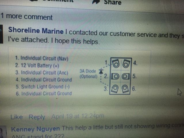
This is what I got off their FB page.
I think I now understand it.
Last edited by StarcraftSS; 05-17-2017 at 04:24 PM.
1999 Stratos 273 / '98 Johnson 150hp
Little bit of an odd switch.
So you'll feed 12V to pin 2 and connect the power wire for your pump to pin 3. 12V negative/ground source to pin 5. If your pump doesn't already have a negative wire in place, you can run one from pin 6.
The source of your 12V will possibly need some planning.You'll want to find a power source that is only hot when the master switch is on. There may be extra stub wires under the console or you may have to hunt around or tap into the master switch.
If you have integrity, nothing else matters. If you don't have integrity,
nothing else matters.
you don't have a true 6 pin DPDT lighted rocker switch. You have a 6pin rocker switch design for the anchor lights and running light circuit. As Catfan said above, this switch is set up for a ground circuit to be carried on the right side and the running lights on the lift. The optional diode allows the pins 1 and 3 to connect when the switch is placed in one direction to give both anchor and running lights, but in the other direction, the diode blocks the circuit and allows for a connection to just the anchor light. Again, with the right side as the ground, this will make the lighted switch light when the switch is turned either direction.
John
BBC Sponsor since 2006: (870) 773-3474
Mon - Thrs 8am - 5pm Central
Friday 8am-12pm
Garmin Certified Dealer and Installers: Call us for all your Garmin Electronics needs!
ASC for: Garmin, Lowrance, Minnkota, Humminbird, and Powerpole.
[SIGPIC] http://www.jonestrollingmotor.com
[/SIGPIC]
It's installed in the dash now...so I'm not going to change the switch now. No biggie..if I don't end up using the other 1/2 of the switch.
All wiring has now been run and I'm awaiting the arrival of the recirc pump(Friday).
Catfan,
Power is going to be coming from a separate 12v battery...that powers my fish finders.
1999 Stratos 273 / '98 Johnson 150hp
Be sure you have the power feed fused.
If you have integrity, nothing else matters. If you don't have integrity,
nothing else matters.
Hooked up a spare pump to wiring to test switch. When I press "red" side of the switch down...the "amber" side goes up(obviously) and lights up...and the pump runs correctly. Have no idea if I wired it wrong...or this is how the switch is designed to light.
1999 Stratos 273 / '98 Johnson 150hp


 Reply With Quote