The lines never showed up until dedicated down elements were added. They go away when you use a different frequency for side and down and they don't show up on the new hummingbird units that have chirp for side and down


The lines never showed up until dedicated down elements were added. They go away when you use a different frequency for side and down and they don't show up on the new hummingbird units that have chirp for side and down
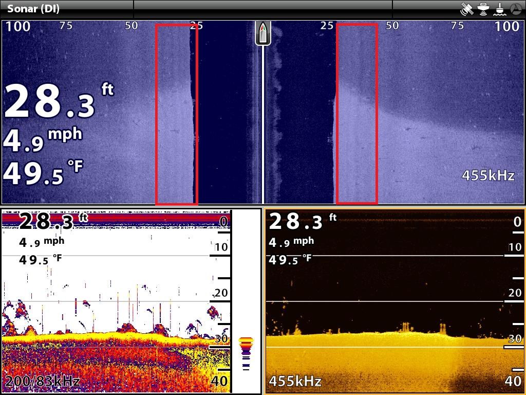
Dedicated down element does not effect on two big false shadows on SI views of LSS-2 unit (see below). I hope we will see confirmation soon when Rickie turn off DI, and we will see what happens with SI views and theirs false shadows.Originally Posted by TroyBoy30

No clue what you're talking about. I'm talking about the waffle affect
These occurs when a unit with a dedicated down element is pinging the same frequency as the side element. It's very pronounced on garmin units. Humminbird showed it the least. They are non existant now since they are chirping side and down

We are not talking about the same thing. Your statement about a false shadow being caused by a gap in the beam/lobe may or may not be true. I don't know. Your pic to illustrate blurring due to triple overlaid is in error. Granted the DI is blurred but possible for a different reason. Multiple objects the same distance from the xd will be blurred for DI. Has nothing to do with overlaid. The wider the DI cone and the more objects to the left and right of the centerline of the cone the more blurring. An inherent weakness of DI. On SI the wide cone is an asset. The only confusion (blurring) would be from objects the same distance from the transducer that are up in the water column. A suspended brush halfway to the top would produce blurring on SI. Go over a suspended brush on DI and it would discriminate between it and the bottom. It's not about overlays. It's just cone angles and distances to objects.
My wife asks if I'm going to fish every day. I can't fish every day. Some days I might be sick.
Exactly. You get the exact same effect when you create or simulate a DI image from two side elements, so it makes no difference if you have one, two or three elements.
Every single return on the left side of the boat gets drawn on top of every single return from the right side of the boat - every single time.
It doesnt matter if you are using GT transducers, CV transducers, LSS1, or LSS2, etc. Thats just the way DI is.
If you are getting returns from the SI elements, they will also be drawn on top of the other returns, but they wont make it more blurry. The SI elements are not far enough from the DI elements to cause any change in distance of the return. They will add to the depth shown below the "bottom line" because they are hitting targets further away. Distant targets do not get drawn on top of closer targets.
Edit: actually, it occurs to me that, in theory, creating a DI image from two SI elements should be worse than from a single element because the elements are separated. That difference in distance has more potential to cause blurring than you would ever get from a single element.
Plus, I just thought of another point in favor of single elements. If two element DI was all that great, why has every single manufacturer gone to so much trouble to add dedicated DI elements and promote them as better?
Last edited by Larry3215; 06-25-2017 at 08:01 PM.
Smokercraft Phantom 202 Yamaha F115/Merc 9.9
Garmin 7610xsv/GT51M-TM/Panoptix PS21/LiveScope
Why am I hanging out here when I could be fishing.....
My plan is to connect the LSS Cable and scan a course (or several) with LSS, Structure Scan HD, Sonar Hub, built in Touch sounder with the LSS 1 xducer and the LSS 2 xducer ...
Then remove the DI pin in the LSS cable and repeat all of the above ...
Rickie
Thats sounds good.
Is there going to be an easy way to possibly disconnect the SI and do a repeat pass with DI only?
Dont forget to set the depth on DI well beyond normal so we can see the bottom fadeout and judge how much extra, if any, is added by SI signals.
Smokercraft Phantom 202 Yamaha F115/Merc 9.9
Garmin 7610xsv/GT51M-TM/Panoptix PS21/LiveScope
Why am I hanging out here when I could be fishing.....
I said several times here that single element DI or dedicated DI is better than two element DI, and much better than three element DI firing at the same time:
http://www.bbcboards.net/showthread....=1#post8515915
"...at this point I am explaining that two element CV CHIRP DI potentially could be better at those depths and even much deeper, than Lowrance triple overlaid DI. But it can not be better than GT52 DI because it is definitely dedicated DI view"
and several times that Lowrance three element DI is not a dedicated DI (GT52 is), but it is an overlay of left and right SI beams returns (as two element DI does) plus central beam overlay - triple overlay. The more overlays the more risk of getting blurring because of elements misalignment, and getting double-triple contours (shape ) of objects above bottom line.
At this point, taking in account guaranty of not missing anything below boat, I would place them so:
1. Single beam DI.
2. Three beam DI.
3. Two beam DI.
at the moment we have examples of good CV CHIRP DI working at 30ft, if I get evidence that the two element CV CHIRP DI works properly at 90-100ft I would move it to the second place.
Last edited by vik; 06-26-2017 at 02:37 AM.
That would take another $60 cable (after I pull the DI pin in this one) ...
Rickie
Oh, ok. Not worth that much extra expense for sure.
Smokercraft Phantom 202 Yamaha F115/Merc 9.9
Garmin 7610xsv/GT51M-TM/Panoptix PS21/LiveScope
Why am I hanging out here when I could be fishing.....
What if you opened up the cable and cut the DI wire instead of pulling the pin? Then you could solder it back together, and cut the SI wire. When you're all done, solder the SI wire back and you are left with a fully functional cable. That would only work if you knew which wire was which though.
Smokercraft Phantom 202 Yamaha F115/Merc 9.9
Garmin 7610xsv/GT51M-TM/Panoptix PS21/LiveScope
Why am I hanging out here when I could be fishing.....
Just had a thought - which can sometimes be risky - but you could wire in a DPDT switch (Double Pole Double Throw) if you cut the cable. You could wire it so that left position was DI only and center position was both OFF and right position was SI only. Of course, that assumes there are only two signal wires you need to switch ON/OFF. The switch would probably add another $4 - $8 bucks from Amazon or even an auto parts store.
Edit: Wasnt thinking that all the way through. Need an option for both ON... have to work on a simple way to do that later. Have to run the grand kid to horse camp....
Smokercraft Phantom 202 Yamaha F115/Merc 9.9
Garmin 7610xsv/GT51M-TM/Panoptix PS21/LiveScope
Why am I hanging out here when I could be fishing.....
Sometimes this stuff gets a little more complicated than at first glance. The way I made the switch to switch from the LSS1 to the Hbird compact xd was using extension cables to avoid cutting into the transducer cable. Seems I remember first wiring it wrong as I had the color code for the wires-pin for the transducer and assumed the extension cable used the same color code. Nope!! Of course once you cut the extension cable it's a simple continuity test to match the color to the pin. For each element Lowrance runs two wires; one for signal and one for ground. Hbird is different, one for signal for each element and one common ground for the whole xd. Rickie, I have the pinouts if you need them.
My wife asks if I'm going to fish every day. I can't fish every day. Some days I might be sick.
There are so many anomalies that can be induced into xducer cabling that is not properly sealed....
I feel the most certain testing results will be from cabling that has not been opened, spliced, or otherwise compromised of the shielding and separation of the channels inside the cable sheath ... Pulling the DI pin should not compromise the cable integrity ...
----
Thanks Leonard ... I have the pinout ...
Rickie
Last edited by rnvinc; 06-28-2017 at 08:37 PM.
Ah well, not the best idea Ive had recently then :)
Smokercraft Phantom 202 Yamaha F115/Merc 9.9
Garmin 7610xsv/GT51M-TM/Panoptix PS21/LiveScope
Why am I hanging out here when I could be fishing.....
Ok, just to complicate things, I found out that Garmins GT transducers all have the element array tilted to port 16 degrees.
http://www.thehulltruth.com/marine-e...ansducers.html
Im going to have to look at some of my screen shots in a new light now and ponder this new information......Answer:
The current production GT downvu transducers use a 3-pc array that is rotated to port side 16degrees. Provides a bit of shadowing effect without affecting depth performanc
Smokercraft Phantom 202 Yamaha F115/Merc 9.9
Garmin 7610xsv/GT51M-TM/Panoptix PS21/LiveScope
Why am I hanging out here when I could be fishing.....


 Reply With Quote