Results 1 to 14 of 14
  1. #1

    G2 with Dual Teleflex Issue

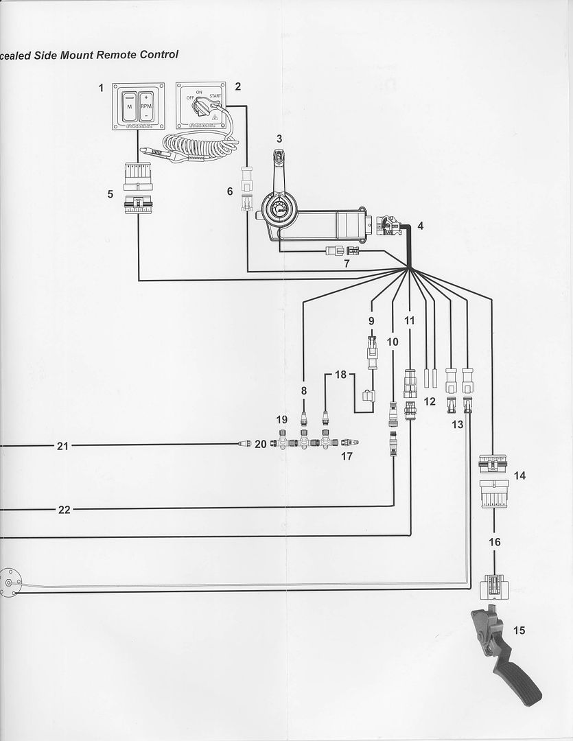
    Not really a motor issue I don't think but I have a G2 with a dual teleflex (tilt/trim and hydraulic jack plate) set up....The jack plate side works fine but my tilt/trim is intermittent. The tilt/trim on the controls and on the motor both work fine. Seems to me like a connection somewhere is bad? Does anyone know where I should be looking?

  2. Member 86 inches's Avatar
    Join Date
    Feb 2011
    Location
    Phoenix, AZ
    Posts
    4,002
    #2
    Not a professional but I would first check the terminal connectors on the protrim unit. Then, I would check the y-adapters. If you also have a bow trim switch, then there will be two y-adapters daisy-chained together. Check both and their connection to the CSM. If all connections are tight, you might have to disconnect them and check the continuity of each. The y-adapters use Deutsch connectors which are pretty solid connections but maybe one wasn't 'clicked' into place during install and has now worked loose.
    1994 201 Champ re-powered with a 250 HO G2 E250LHAFA 05438419


  3. Member 86 inches's Avatar
    Join Date
    Feb 2011
    Location
    Phoenix, AZ
    Posts
    4,002
    #3
    I suppose you could also check the protrim switch itself by swapping the terminal connectors for the trim side switch with the connectors on the jackplate side switch. However, you MUST swap all three connectors from each side. The red center wire on the jackplate CANNOT be used on the trim switch. The red wire on the jackplate side is 12V whereas the red wire on the trim switch is a "common" wire which utilizes the network and carries low current. If you connect a 12V power wire to the center connector of the trim switch, you will likely fry something in the CSM.
    Last edited by 86 inches; 02-23-2017 at 08:07 AM.
    1994 201 Champ re-powered with a 250 HO G2 E250LHAFA 05438419


  4. #4
    Ok...Cool...Good info...Thank you

  5. Moderator SEAHORSE's Avatar
    Join Date
    Jun 2004
    Posts
    9,638
    #5
    86 inches is correct. A G2 uses the control network to activate the tilt and trim. It does not swich 12 volts like other systems do


    How to connect a steering wheel mounted accessory T&T switch to the control head harness:
    – Use splitter P/N 176534 which plugs in between the control head harness & the control head T&T switch. . It provides an additional deutsch connector that you connect to the wires from the steering wheel mounted switch. Connect red to red, blue to blue & green to green.
    Note: If the installation requires adding a bow panel accessory T&T switch & steering wheel mounted accessory T&T switch, 2 splitter’s, P/N 176534 are required.
    Install the 1st one as shown. Connect the 2nd one to the open connector of the first one. Connect the 2 accessory trim switches to the 2 remaining connectors. DO NOT CONNECT AN ACCESSORY T&T SWITCH TO THE CONTROL HEAD TRIM SWITCH CIRCUIT IN ANY MANNER OTHER THAN THE PROCEDURE DESCRIBED ABOVE
    -----


    A Technical troubleshooter possessing more tools than talent !

  6. #6
    Thanks Seahorse....Going to try to fix it this weekend.

  7. #7
    Seahorse...Do you happen to have the figures/diagrams that go along with the installation instructions? Can I find this somewhere in a manual?

  8. #8
    I bought my boat used and had a 15 model G2 on it...The tilt/trim never worked at the bow of the boat when I had it...I upgraded to a 16 model G2 and had the marine fix the tilt/trim at the bow of the boat. I believe the tilt/trim worked at the helm for a little while after they fixed the bow panel and then it started to work intermittently...I'm thinking it has got to be a rigging issue?

  9. Member 86 inches's Avatar
    Join Date
    Feb 2011
    Location
    Phoenix, AZ
    Posts
    4,002
    #9
    It's not in the manual and I haven't seen a diagram that shows it but...

    It's very simple once you get in there and do it. There is a 3 position Deutsch connector on the CSM harness labeled "Trim". On an installation where there is a single trim switch in use - ie the trim switch on the CSM remote handle - the wires coming from that switch will be plugged into that Deutsch connector with its mating connector. There are 3 wires coming from the CSM remote handle trim switch (red, blue/stripe and green/stripe) and they will be inside expandable sleeving and will have a three position Deutsch connector at the end.

    On installations where, in addition to the trim switch on the CSM remote handle, there is also a bow console trim switch, there will be a short Y-adapter harness maybe 12 inches or so long. There will be a 3 position Deutsch connector at the end of each branch of the Y-adapter. The Deutch connector on the end of the "bottom" of the Y will be plugged into the Deutsch connector marked "trim" on the CSM harness. At the "top' of the Y, one Deutsch connector will be mated with the connector from the CSM handle trim switch and the other Deutsch connector will be mated with the connector coming from the bow console trim switch.

    On installations where there are three trim switches: one on the CSM remote handle, one on the bow console and one on the steering column, there will be two Y-adapter harnesses daisy-chained together; the Deutsch connector marked "trim" on the CSM harness will be mated with a connector at the 'bottom' of the first Y. At the 'top' of this Y, one Deutsch connector will mate with the connector at the 'bottom' of the second Y-adapter and the other will mate with the CSM remote handle trim switch. Going up to the 'top' of the second Y, one connector will mate with the connector of the bow console trim switch and the other will mate with the connector of the steering column trim switch.

    The wire colors from each harness will match the other at the mating Deutsch connectors; red to red, blue/stripe to blue/stripe and green/stripe to green/stripe. Red is "common" - NOT 12V - and if I recall correctly, blue/stripe is trim up and green/stripe is trim down.

    Here is part of the wiring diagram from the I & PD guide. Connector (7) is the trim switch connection. If Y-adapters are used, this is where they will be inserted. This diagram shows a single trim switch on the CSM remote control handle (3). The CSM harness is (4) This diagram shows the orientation of a starboard CSM with the body of the unit reversed and directed aft. That is how I installed mine. It is very likely that your Ranger has the body of the CSM directed fore. You will have to either find the CSM harness and work toward your trim switches or you might prefer to start with your trim switches and work back to the CSM harness.

    Check to be sure that each Deutsch connector couple is snapped together completely. You might want to separate each connection and visually verify that each individual pin and socket is fully inserted into their respective housings. It's possible that one of the pins or sockets didn't get clicked fully into position in the housing and got pushed back when the two housings were connected.


    I believe this is a pic of the Deutsch connector on the CSM remote handle trim switch harness. It is a 3 position receptacle with pins (DT04-3p), if I recall correctly. The connector on the CSM harness will be a mating 3 position plug with sockets (DT06-3s). The color of the Deutsch connectors might be black (like the one shown here) or grey. The housing color doesn't matter. Deutsch connectors are marked DT (series prefix) 06 (plug) or 04 (receptacle) -3 (number of contacts) P (pins) or S (sockets) Plugs use sockets and receptacles use pins.


    Your connectors might be grey like these.


    The wires will look like this but will be in black expandable sleeving. This pic shows what I remember to be the pins of the CSM remote handle trim switch wiring.


    I'm doing this from memory as my boat is in the shop right now. It's possible that I have my pins and sockets backward. I believe the Deutsch connector on the CSM harness is a plug with sockets and the Deutsch connectors on the wires from the switches - and also on the 'bottom' of the Y adapters - are receptacles with pins. The 2 connectors at the top of each Y adapter should be plugs with sockets.

    I think the y-adapters (part number 176534) run about $35 to $45. You can make your own with Deutsch connectors (prowireusa.com is where I get them). I get the 14-16 g solid pins and sockets and use this $35 tool;

    Eclipse Tools 902-499 Eclipse Tools Crimper for Deutsch Terminals.


    This tool is kind of handy too;

    DT DTM DTP Wedgelock Removal Tool.


    I am not a professional. You should ask SEAHORSE or ChampionMan to confirm.
    Last edited by 86 inches; 02-23-2017 at 08:03 PM.
    1994 201 Champ re-powered with a 250 HO G2 E250LHAFA 05438419


  10. #10
    That's good stuff right there! I appreciate it so much and I'll report back with how it goes. Thanks again man...Great info.

  11. Member 86 inches's Avatar
    Join Date
    Feb 2011
    Location
    Phoenix, AZ
    Posts
    4,002
    #11
    I don't know if you finished your project yet or not but I was into my wiring today connecting up a new blinker trim and I snapped this pic. I thought it might help you.

    1994 201 Champ re-powered with a 250 HO G2 E250LHAFA 05438419


  12. #12
    Thanks for the picture...I've been procrastinating...I need to get after it! Lol

  13. Member 86 inches's Avatar
    Join Date
    Feb 2011
    Location
    Phoenix, AZ
    Posts
    4,002
    #13
    Quote Originally Posted by bassmasterffej View Post
    Thanks for the picture...I've been procrastinating...I need to get after it! Lol
    The last pic shows the 2 y-adapters daisy chained together. The open deutsch connector is where the blinker trim plugs in. The unlabeled connector with the wires going back into the access port is the harness for the CSM trim.
    1994 201 Champ re-powered with a 250 HO G2 E250LHAFA 05438419


  14. #14
    Thanks man...You have a big a HUGE help.