This thread is locked, please reply with any questions with a new topic.
Contact Lowrance
How to Obtain Service in the U.S.A.
Contact the Factory Customer Service Department:
1-800-628-4487
Mon-Fri 8:30 AM-4:45 PM Central Time (closed holidays).
Support web page
http://www.lowrance.com/en-US/Contact-Us/
Lowrance Canada
1-800-661-3983
for both technical and warranty support for Canadian customers.
------------------------------------------------------------------------------------------
Networking Lowrance units with NMEA2000 (Lowrancenet)
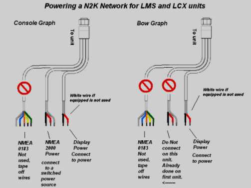
First and foremost, the NMEA Network requires its own power connection to operate. It does not get power through
the unit itself. The older LMS and LCX units had a set of wires on the unit power cable which could be used to power
your network, this cable is labeled NMEA 2000 Power on a tag affixed to the cable.
HDS units require a power node to give power to the network. This comes in the starter kit or can be purchased
separately. HDS units can not get NMEA power by using a LMS or LCX power cable. A power node can be seen in the
diagrams below. Most important of all >Never use more than one power source for the NMEA connection.
Never apply two sources of power to the same NMEA network. If you have one unit or four units connected to a
network it will require one NMEA power connection to operate the entire network. This is probably the biggest
mistake made by most people, adding additional units to the same network and powering the network again.
This will damage anything connected to the network. So always be sure your NMEA network is only getting power
from one source no matter how many devices are attached. Cap off any older units nmea power cable and tie it
back under the dash.
>>>The NMEA Network power must be put on a switched power source so you can shut it off when not in use.<<<
----------------------------------------------------------------------------
This power cable diagram does not apply to HDS units it is meant for the LCX/LMS units.
Some boats come pre-rigged withe NMEA2000 network backbone from the boat manufacturer and may use a Power Node to supply power the network. This Power Node is hooked directly into a Tee in the network bus. If your boat has one of these on the network DO NOT power the NMEA power wires from either graph. It is already done. Powering it twice will cause damage to the Module, graph and any sensors. Below is a picture of a Lowrance power node for powering the NMEA2000 backbone on a red/black network. You can see in the diagrams further down how it connects to a T in the network. It is recommended to connect this to a switched power supply so it can be shut off.
Lowrance power node.jpg
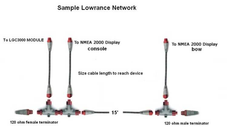
Note** HDS Models would require a Power node to supply power to the Network Bus. This diagram below shows the network bus configured for networking 2 LMS or LCX units to one GPS module. In this case you would power your nmea network by connecting one of your LMS or LCX unit power cables marked NMEA 2000 Power to a switched power source. Important to connect this power from only one power cable, any additional units on the network just tape the nmea power wires off individually.
Please note these diagrams are older and will work for the Elite 7 models that have N2K capability. Also the Point 1 GPS module is a replacement for the LGC line and will work just fine in any N2K configuration.
------------------------------------------------------------------------------
Networking HDS Models with NMEA2000
The Diagram below shows adding an external antenna, which is optional. If you are not hooking up an external antenna get rid of the extra Tee in the diagram.
Please note if you are only interested in waypoint sharing all you need to do is connect the two HDS units with an Ethernet cable. No NMEA Network is required unless you are using network sensors like temperature, fuel, interface cables or an external gps module.
The NMEA Network is totally expandable, just remove the terminator, add a Tee to plug in your new sensor or unit and replace the terminator back on the new end. It's that easy!
Two HDS units Networked
* if you are still using an older LMS or LCX unit which is networked to an HDS unit it can still power the nmea network through its power cable. (HDS units can not do this) If you are switching to all HDS units you have to buy the NMEA Power node to power the network, shown in the diagram below.
One HDS unit with LGC-4000 antenna
This diagram could also be used as a guide for One HDS unit with Sonic Hub or two Elite 7 units for waypoint sharing...
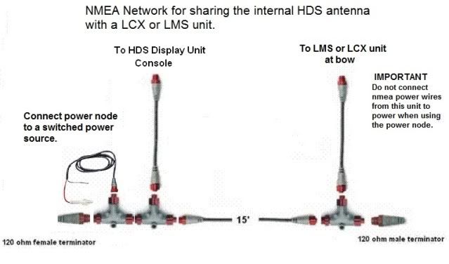
Network HDS to LMS or LCX unit to share the HDS internal GPS antenna
Network adaptor cables. Which one do I need?
Red to blue? Blue to red?
http://primus.lowrance.com/icr/NMEA%...0_adapters.htm
Parts needed to network two HDS Models:
1) NMEA Starter kit: N2K-EXP-RD-2 (#124-69)
kit includes: Includes 2 terminating resistors (TR-120M-RD, TR-120F-RD),
two T-connectors (N2K-T-RD), one 2 ft extension cable (N2KEXT-2RD),
and one 15 ft extension cable (N2KEXT-15RD), and a power node (N2K-PWR-RD).
$51.99*
1) T connector, N2K-T-RD #119-79 $14.99*
* prices at time of posting from
------------------------------------------------------------------------------------------
Waypoint sharing between units, clarification
Waypoint sharing with LMS or LCX units: A NMEA 2000 network must be used to share waypoints between these units. Ethernet will not allow waypoint sharing, only HDS models can use Ethernet for waypoints. Waypoint sharing with these older models will not automatically transfer all of your waypoints from one unit to another unit. This must be done manually with a card. Waypoint sharing works "one at a time" as you first create the waypoint, it will then transfer that data to the other unit. Both units must be powered on for it to transfer.
Wapoint sharing with HDS models: Ethernet will share waypoints as well as NMEA 2000. But with the Ethernet you will have advanced or enhanced waypoint sharing and editing which means the two units will auto synch with each other once connected and turned on. No manual tranfers needed. This is a great feature. You can edit a waypoint on one unit and the changes are made to the other(s) automatically once they are turned on. Other units do not have to be on during waypoint creation. Once connected it will synchronize the other units.
Please note that the HDS5X model can be used to create and send a waypoint to other units in the network as long as it is networked to another unit which has GPS by using a NMEA2000 or 0183 network. Ethernet alone will not allow a 5X model to send waypoint information.
------------------------------------------------------------------------------------
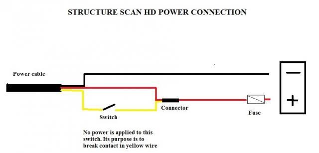
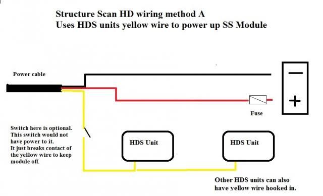
Wiring options for Structure Scan HD Module
In this wiring method you must place a switch on the yellow wire to break power contact or the module will run continuous.The switch is not a powered switch, it just breaks continuity in the yellow wire.
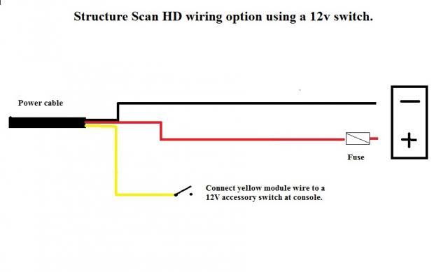
With this wiring method you will connect the yellow wake up wire of the SS HD module to a 12 volt powered accessory switch. It must be turned on to power up the module. This is a nice quick way for those who already have an unused accy switch on their console and wish to keep the SS power independent from the unit power.
With this option the yellow "wake up wire" from each HDS unit is connected to the yellow wake up wire of the module. Powering up any HDS unit will turn on the module. When multiple units are connected in this fashion the first unit turned on will start the module and the last unit shut down will shut off the module. Adding a switch on the yellow wire of the module is an option and will benefit those who may want to keep it from turning on and still use their units for GPS or 2D sonar. Note the switch is not a powered switch, it just breaks continuity in the yellow wire of the module when shut off.
------------------------------------------------------------------------------
Updating software in older units which came with the LGC2000 GPS Module
Before doing the update to the unit you must make sure the update to the LGC2000 antenna is done first. This is very important. Read the update instructions page for the LGC2000 antenna, it tells you how to identify which version your antenna currently is using. If you do not update the antenna before updating the unit you will lose connectivity with the antenna and have to get it fixed or possibly replaced.
I would suggest that you verify the antenna update has completed successfully before moving on to the next step of updating the head unit.
Use a smaller size SD card for updating older units using the LGC2000
Some older units worked better if the card was smaller than 1 gig, a 256mb or 512mb SD would work great.
A Software update instructional video posted on Youtube
An HDS unit software update tutorial video from Lowrance
Link for information on HDS Insight Mapping
http://primus.lowrance.com/sup...Goto5
-------------------------------------------------------
Viewing your unit from inside your house:
First you will need an extra power cable for your unit. You can purchase the regular power cable or get one that has the cig-lighter end on it. There are a few ways to power it from inside but i went to Radio Shack and bout a power supply w/lighter socket outlet. That part no is 22-165 and got the lighter plug to connect to my power cable and that part number is 270-035. Always make sure you have the correct fuse size for the unit.
Power supply: Enercell 12V/1A Power Supply w/ Vehicle Power Socket : Power Supplies | RadioShack.com
Lighter Plug: Enercell 12VDC/7.5A Vehicle Power Plug w/ LED : Vehicle Power Plugs | RadioShack.com
Setting up HDS 2D Sonar and Structure Scan - By Jason Gilstrap (Lowrance ProStaff)
Jason has put together a video on his website on setting up your unit. Click on the link below to view:
Tips on Lowrance HDS 2D Sonar and Structure Scan Settings